and method of repair of one of my Newbrain ADs bought on eBay.
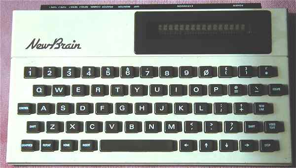

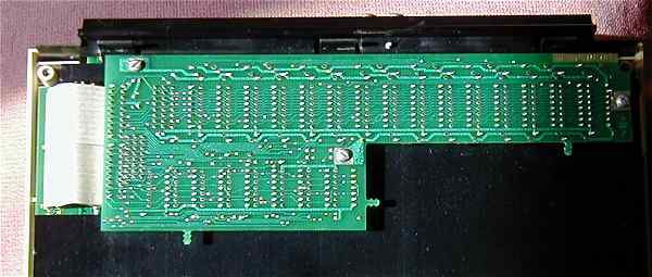
Unscrewing the four screws holding the base in place, with a small straight edged screwdriver, allows you to remove it and reveals the main RAM board attached to the large sheet of anodised aluminium, which acts as the main structural element, or core to the machine. The multiple ribbon cables attaching the RAM to the main board are clearly visible on the left, as are the three screws holding it in place. From the back of the case, lifting up from the left hand side very carefully should pull the main board up and away. Care should be taken to lay this over on the right hand side, so that excees strain on the ribbon cable attached to the keyboard is avoided, see below. You will now see the five screws holding the main board to the aluminum core. Removing these will allow the board to be separated from the aluminium sheet at the front to give better access to the two capacitors that need to be replaced.

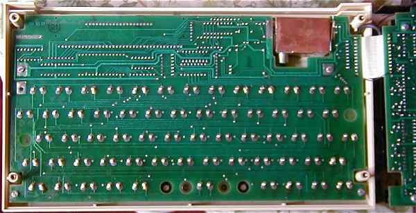
Above, a view of the keyboard back, with the paxoline sheet removed. This displays the number NB 12125/A/3, which contrasts with the Model A, displayed on the home built page, which is NB 12127/A/3. The long line of connections for the display clearly shows the very different layout ,as compared to the A Model.
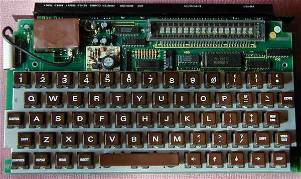
Front of the total unit removed from it's case. The multiple connections to the display are clearly visible, as is the black, coaxial cable connecting the UHF modulator with the TV out phono socket. The high voltage power supply for the flourescent display is also visible as the small cream coloured circuit board. This is shown in greater detail below.
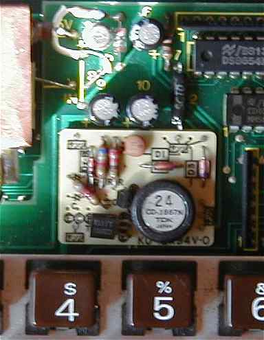
This close up of the power supply, shows that it is a discrete unit. Manufacutured as a standard individual component by TDK, these were bought in large numbers, probably to reduce individual costs. When in the hands of the reciever, they were sold to Greenweld. They obviously did not sell well, and a large stock of them got passed on to the new Greenweld company. I recently bought a pack of three in a sale, as item Z1699, and they are possibly still available, if your display has failed to light up. If not, contact me and I could let you have one just for the postage.
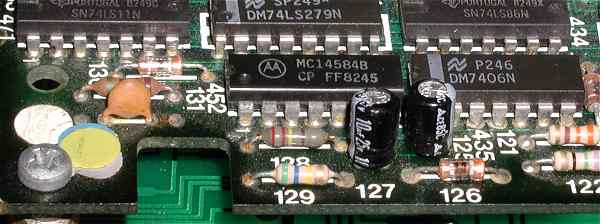 These are the capacitors in question. They are the black cylindrical electolytic, can capacitors of 10microFarad, 24v value, 127 & 125. Their gradual drying out changes their value and prevents the Newbrain from resetting properly. Consquently, if you get a display at all it is just a jumble of random characters. The three dead machines which I have resurrected, sprang imediately to life when they were replaced. Of these, two initially showed the random characters the other appeared to be totally dead.
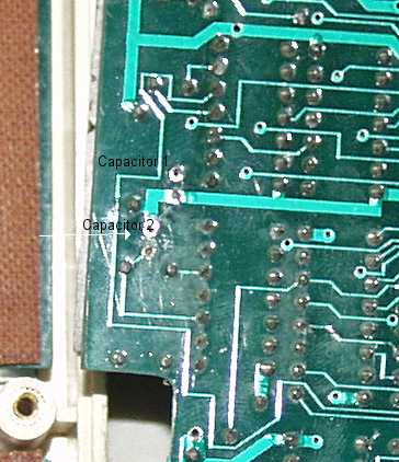 The above view is taken from the right hand side of the back, the screw head shows the position of the extreme corner. As doumented above, removing the 5 screws, will enable you to get a better view of them. Don't be tempted to remove the screws attaching the power transistors at the back. It is not necessary, and they are difficult to replace, YOU have been warned!! The view on the right shows the track surface of the PCB, with the four holes after they have been cleared of solder and the capacitors removed. This is best done with a large solder sucker; make sure that all the solder is molten and then put the teflon tip of the sucker right over the hole and with any luck all the solder will be removed in one go, if not try again. Make a note of their polarity (marked with a '+' near the respective lead, then push the freed leads back and forth a bit with the soldering-iron tip, to make sure they are loose, the capacitors can now be easily leavered out. They should be replaced with Tantalum Bead capacitors of the same value and with exactly the same polarity. On the ones I purchased from Maplins, a small vertical line on the body of the bead, marks the positive lead. If you haven't got a Maplins near you, they can be ordered on line from their excellent Web Site The item number is WW69A and they cost 49p each, so repair your Newbrain for less than £1. The Tantalum devices have the same tolerance (20%) as the electrolytics, but have a much better long term stability. AGAIN, if you don't feel up to what is quite a tricky replacement to those not used to soldering, contact me and for little more than the cost of postage, I can do it for you.
