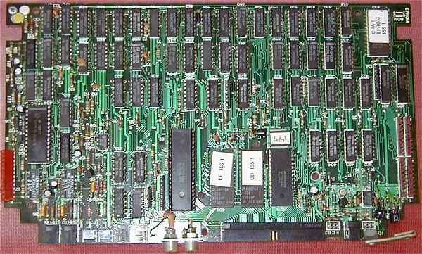
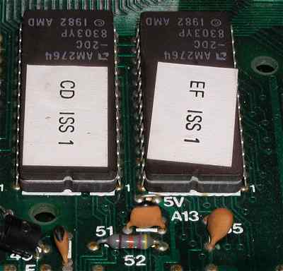
 The complete, and from the production stickers on the top left corner, tested and fully working, main board. This is a very early, version 1 board, with totally EPROM (x2 2764) based operating system and character set (2732), ROMS. It was made possible to switch to mask programmed ROMs using the wired jumper positions in the top right hand corner. I have seen later versions with mixed EPROM and ROM, as well as larger, single 128K ROMs, rather than the two 64K, which may be made possible by a simple link on the board, switching between 5v and A13. To connect the RAM and keybord, not having the original connectors, I attached a Single In Line, short socket to the bottom right ribbon cable position and two rows of SIL pins into the ribbon cable positions for the RAM on the bottom right. You can also see the short length of aluminium I attached to the power transistors used for voltage regulation, to soak up the heat created, as well as the two small electrolytic capacitors I had to move in the far right, bottom corner, as the fouled the RAM card when attached!
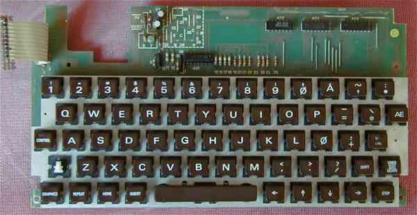
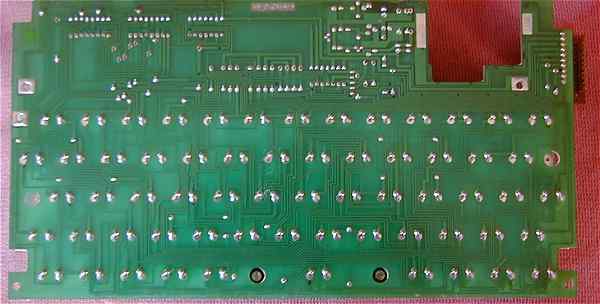


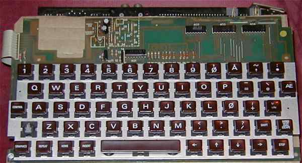
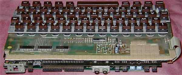
The assembled Newbrain. The main board and key board are bolted together, with two nuts forming the separator, together with the sheet of corrugated cardboard, rather than the paxoline used in the production machines. The extra thickness produced by using sockets for the RAM, together with the SIL connectors, rather than ribbon cable, probably make the asssembly too thick to go in a Newbrain plastic case. It is thus just as well that I decided to mend my broken purchase.
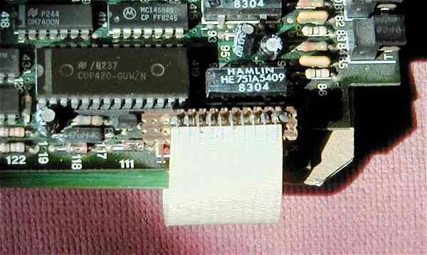
The top, right hand edge of the main board, showing the vero board strip I used to connect to the keyboard ribbon cable. Note also the larger, socketed chip, a COP420, which is a dedicated microcontroller used for keyboard scanning and other I/O facilities.
