![]()
![]()
![]()
![]()
![]()
![]()
![]()
![]()
![]()


All my content and ptohos
PC and compatibles - General information
General PC FAQ by MCbx, 2015-19.
0. AT, XT, PS/2?
1. What to do if battery is leaking?
2. Battery is weak, but there is no visible battery
3. What can be installed in an empty socket near CPU?
4. How to enter Setup?
5. Common memory and cache types
6. Testing memory in old PC
7. Floppy disks and drives
8. Recovering from floppy disks
9. Recording floppy disks from images
10. What slots can be found in the mainboard?
11. What expansion cards do I need for...
+RTC solutions for PC XTs
+Serial and parallel ports and
their brackets
12. Help with configuration
13. Hard disk types in PCs
14. When hard disk's capacity is not fully visible
15. Serial and parallel data transfer cables
16. Transferring data from an old PC
17. Formatting a hard disk
18. Transferring programs to PC
19. Essential software for old PC
20. Year 2000 problem
21. Diacritized characters in DOS
22. Further reading, software archives
In 1981 IBM introduced IBM 5150, a new personal
computer with 8088 CPU. Later they made 5160, a 5150 with some minor
enhancements (and lack of tape recorder port). These PCs and their clones were called XT - eXtended
Technology. XTs have 8-bit ("short") ISA slots, usually 8088 or 8086 CPUs (there
are some rare 286 XTs). In general, nearly all 8088 and 8086 are XTs. XTs
usually have no RTC (Real Time Clock) on board nor BIOS Setup, they are
configured using DIP switches or jumpers present in mainboard. Sometimes a
special software is used. There is another thing you can easily identify XT:
Some of them (usually higher class clones) have lots of ROM sockets. These
sockets are prepared for ROM chips, as IBM's specification included booting from
ROM, usually to BASIC. Some IBM computers indeed booted to on-ROM BASIC if no
bootable device was found (and FDD controller ran into some error so its ROM
faulted) but most of
them switched to CGA text mode and shown a nice message "NO ROM BASIC".
Nevertheless, in the last 25 years the most popular reason of "NO ROM BASIC.
SYSTEM HALTED" message is the fact that primary partition is on the disk, but
it is not set active.
IBM's next step was PC AT, introduced in 1984. AT had fast,
6MHz Intel 80286 processor and could run in protected mode. They had 16-bit ISA
slots ("wide" ones) and could support more devices. Most AT have BIOS setup
program in ROM and Real time clock embedded to mainboard. Only the most critical
parts (CPU type, memory/cache configuration, graphics card) must be configured
using jumpers. Some XT clones may have exchangeable BIOS chips (two BIOS chips
from two mainboards may be swapped and mainboards will run), but no such
possibility exists in most ATs.
Now there is a small subset of XTs with some features of AT (like a 1024Hz
timer). These non-standard computers were used mostly as machine control or
measurement devices.
After AT, IBM introduced PS/2 architecture, oriented around
MCA bus. Generally this architecture was not compatible with AT, used special
hard disk interface and was based on MCA proprietary bus. Because every
expansion manufacturer had to buy MCA specification to make expansions (and IBM
had to accept the expansion), it was
not popular.
If you take an old PC, you will usually find an AT or XT clone inside.
Some Pentium mainboards and later computers may be ATX. This is
not exactly a computer standard, but casing and power standard. ATX mainboards
have many ports and casing has a space for proper rear bracket. ATX computers
need different power supply unit with software on/off function.
Some early PCI systems may have additional connector for powering PCI bus, this
connector may be coming from AT or ATX power supply (yet the situation with ATX
powering PCI is very rare).
There are also two non-standard ways of powering a PC:
- AT with software power-on - used sometimes in IBM computers from mid-90s
- Dell "ATX", which has AT voltages on ATX-like connector. You have been
warned.
|
Early PCs used rechargeable batteries to tick RTC and store Setup data. These batteries were usually 3-3.6V and were composed of serially-linked 3 rechargeable batteries. The idea is good, but after few years these rechargeable batteries will leak. If you see white powder on battery or mainboard, the battery
must be immediately replaced or it may damage the mainboard. Mainboard is damaged by
quick oxitadion of copper tracks and if it's multilayer board it will be
irreversibly destroyed! |
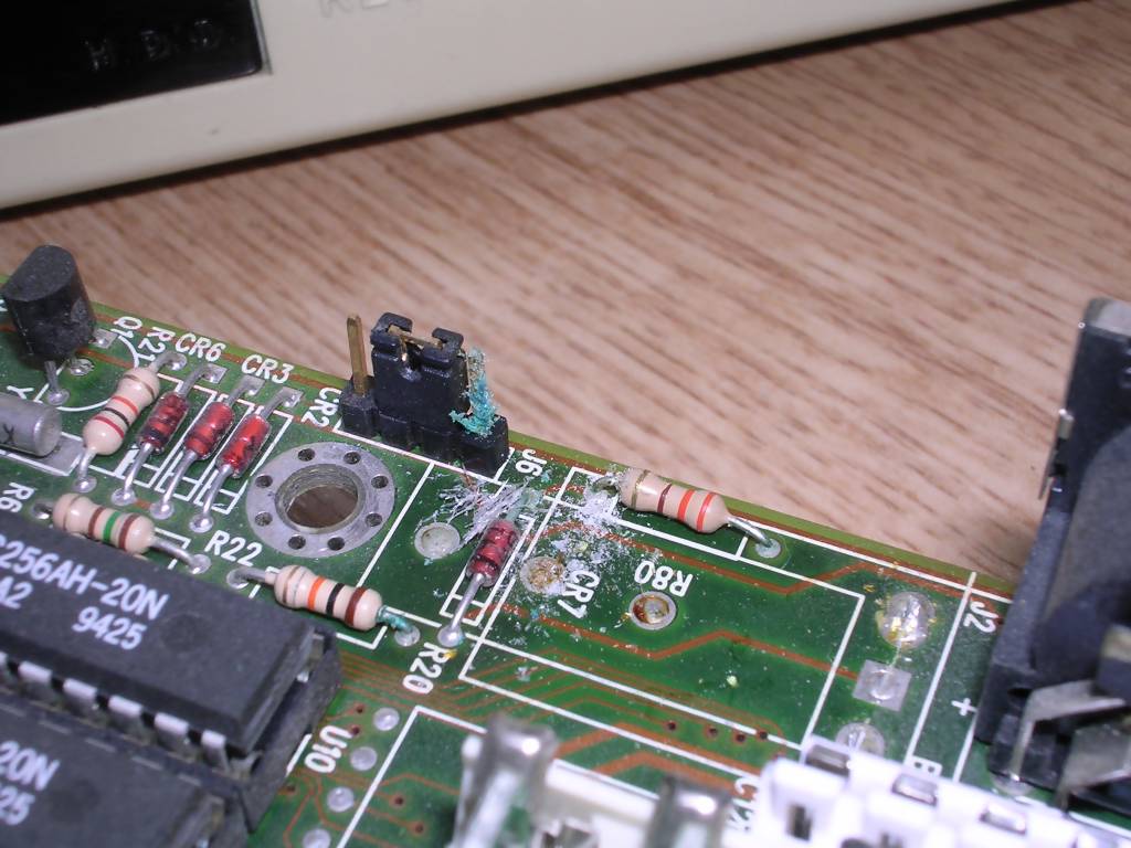 |
First, remove the battery from mainboard. You can use soldering iron or just break weakened soldering points.
Next, using a small brush, clean mainboard off the white powder. Remove chips
from sockets and clean under chips too. This white powder condenses from vapors,
so it will go in all places. Greenish pollution is oxidixed copper.
Then you can replace the battery. It is generally too risky to install this
battery, so it's more convenient to use CR2032. But CR2032 are NOT
rechargeable.
To fix this problem, just install a diode the way that the battery can supply voltage, but cannot be charged. I recommend Schottky diodes such as 1N5819 as they have lower resistance, but a small signal diode can also be used. The installation is shown below:
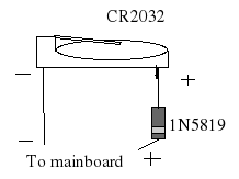
2. I see the battery is weak (RTC stops, BIOS complains) but I can't find any battery!
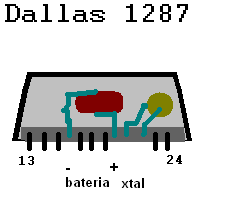
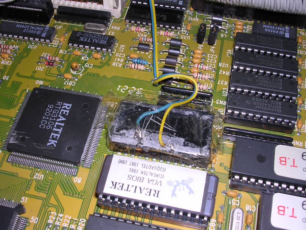
In some PCs Real Time Clock, Setup's memory and battery is embedded in one single chip. The chip is usually marked Dallas 1287, "GRT" or "Odin" and is significantly bigger than other chips. Usually it is trapezoedrical in shape. You can replace or rework the chip. Generally buiying a new chip is a bit hard and expensive and you probably won't know are you buying the chip with good or bad battery, so it's better to open the chip, soler wires to battery connectors and use external 3.3V battery like CR2032. You don't need diode for it as it is not rechargeable, but it is needed to break connections to the old battery (as old battery will drain new one).
This operation should be performed on chip removed from mainboard, but with some practice may be done on soldered-in chips if mainboard is not densely populated. After making the operation, it is needed to protect the area with hot melt glue or insulation tape.
| Let's look what is inside a Dallas chip: 1. The chip, with some pins sticking form the bottom 2. The battery. 3. The XTal - quartz oscillator. The battery and XTAL are connected to chip's pins bent upwards. The trick is to remove the resin and disconect battery's pins from the exhausted battery, then solder own wires to good CR2032 battery. After removing from mainboard, determine pin 1, it is marked by dot. In most Dallas chip, you will have to work on chip's side facing you when markings are upside down. Some "GRT" chips may be different. Now you have to get access and free pins 16 and 20 while keeping all other pins untouched. You can do it by securing the chip in some holder or vice and then saw the casing in few places. Operated side of casing should go off showing resin. |
 |
 |
Now using small, needle-like file (rectangular in cross-section)
go through the resin until you feel the metal. Stop there and using small
screwdriver drill the pin around as much as you can. Using these holes you can
slowly remove pin from battery's side by prying it outwards. But if RTC is soldered in, you have to take a bigger part of casing off. Saw from top along one of longer edges until you go to the resin and then pry off the casing. You now have a resin in which you can carve searching for battery's pins. |
3. What is this empty socket near CPU?
In most mainboards up to 486, you will find an empty socket near
processor. This socket is reserved for math coprocessor, which can speed some
operations up, especially in matematical or CAD software. If you want to install
a math coprocessor, you have to configure the mainboard properly and install the
proper coprocessor in the proper socket. You should use the coprocessor with a
proper frequency, but most of them should work.
In some 386 mainboards you can use a special Weitek coprocessor which has
extended capabilities. It requires specific jumper or BIOS settings.
Early 286 Award: Ctrl-Alt-Esc at startup
Later Award: Del or F1
AMI: Del, F1 or F12
Phoenix: F1, Ctrl-Alt-Ins, Ctrl-S, Ctrl-Alt-S, Ctrl-Alt-Enter (very rare)
Compaq: F10 when a little rectangle blinks in the corner of screen.
Special partition may be needed for Setup to run completely. This partition may
be re-created using dedicated boot disks.
HP: F1 or F2
IBM: F1, Ins, keeping both mouse buttons presset during start-up
Zenith: Ctrl-Alt-Ins
Quadtel: F3, then F1 or F2.
If all fails: Try to run without keyboard, with key pressed since power on or some SIMM
missing. BIOS may take it as
error condition and propose to enter setup.
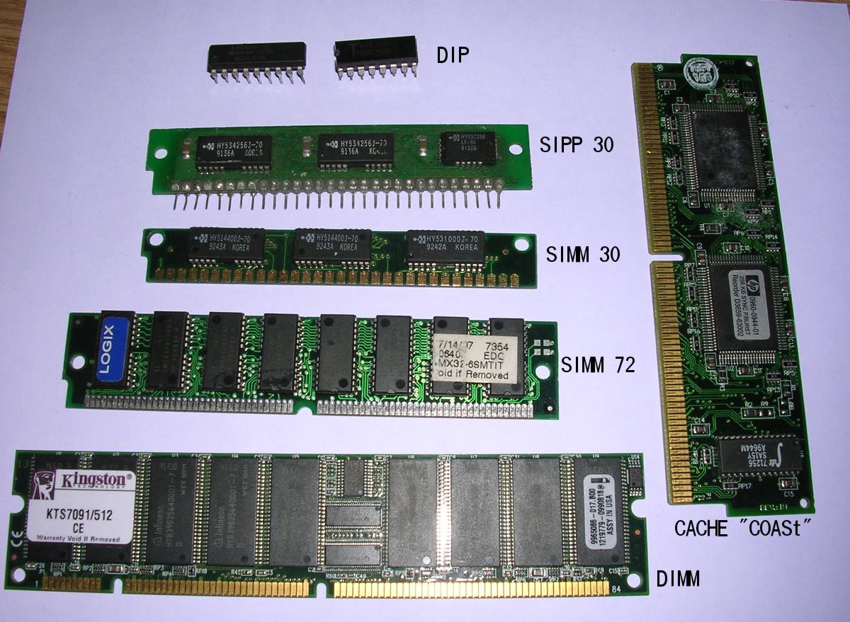 Different types of RAM |
XTs and early ATs used chips in DIP sockets. These are just bare
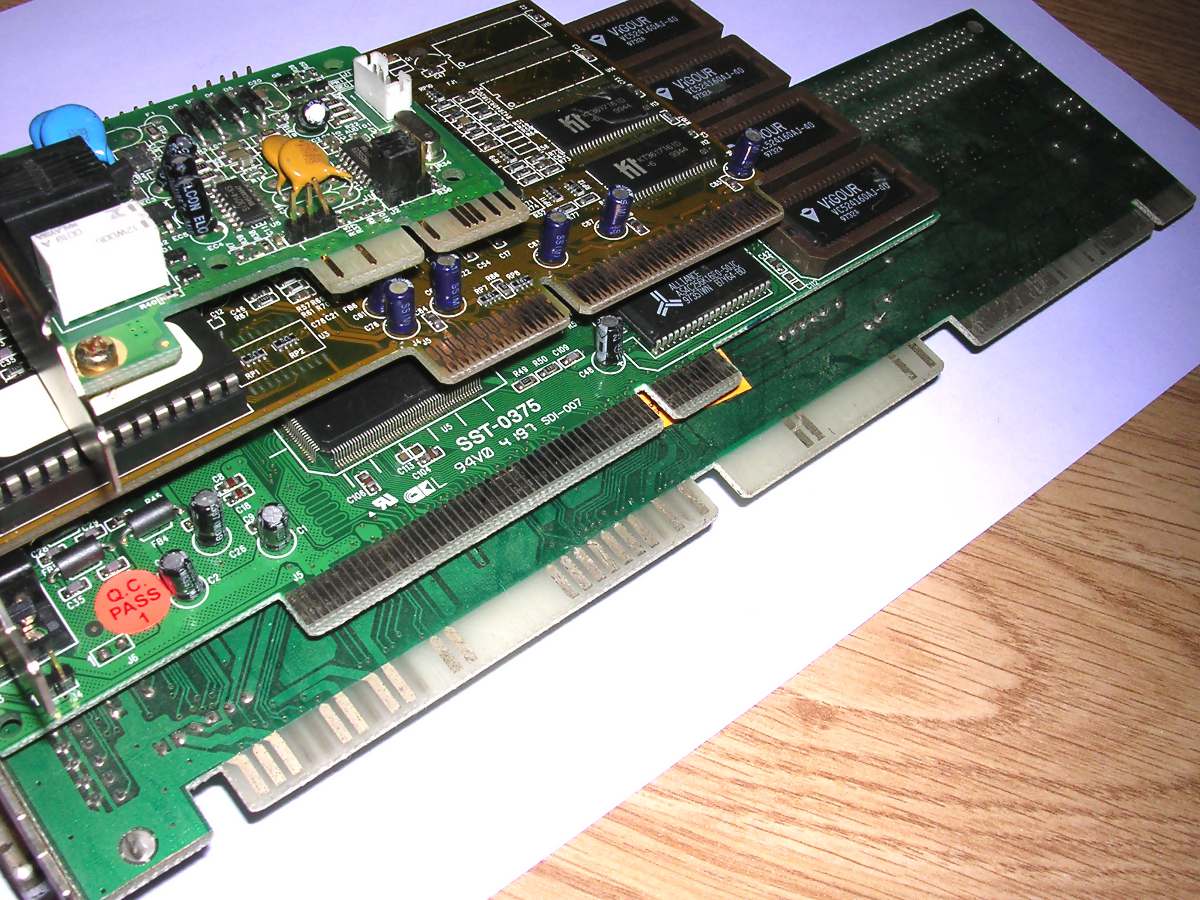
chips in sockets. Most mainboards won't take more than 1MB of these chips. The speed of the chips is usually 80-120ns. Their size is written XxY, where X is length in Y-bit words. You can usually find the following chips: - 256Kx4 (e.g. 44256, 14256) - 64Kx4 (e.g. 4464, 41464) - 64Kx1 (e.g. 4164) - 256Kx1 (e.g. 41256) - 1024Kx1 (e.g. 21010) To check for errors, most old mainboards have additional 1 bit of memory, so for 512kB this will be not e.g. four chips of 256Kx4, but four 256Kx4 and two 256Kx1. In most cases the memory is installed using some kind of 256K chips until 512kB, then using four 64Kx4 chips is filled to 640kB. But of course there are exceptions, some boards can take e.g. 1664kB of RAM in, let's count, 24 chips. |
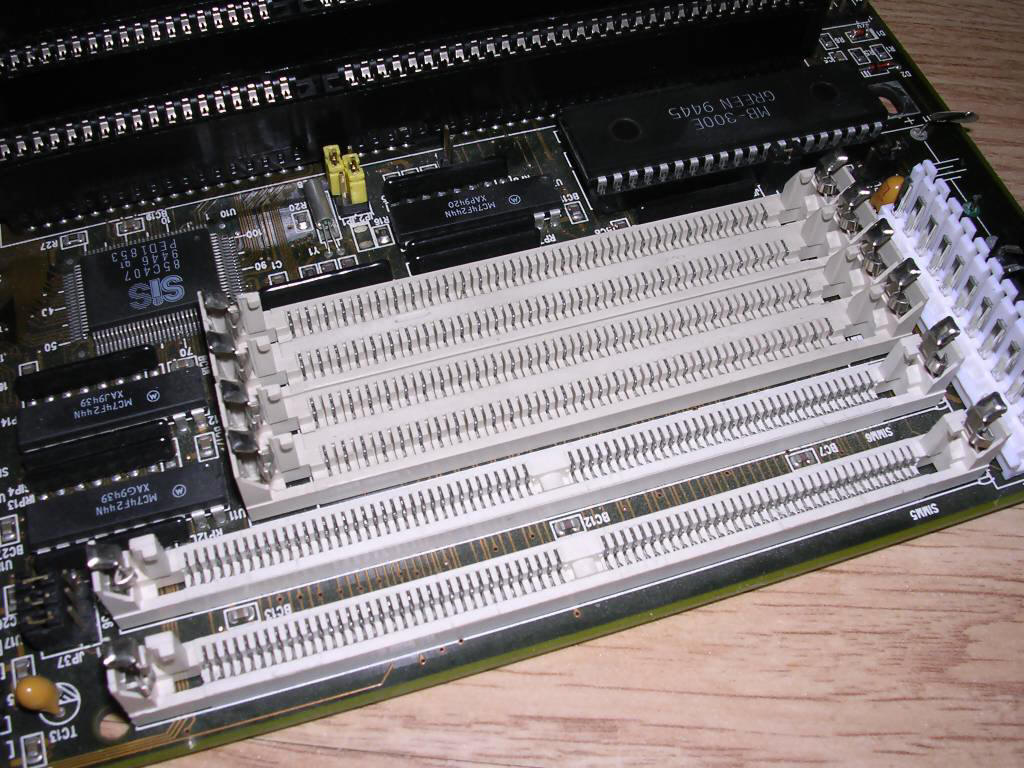
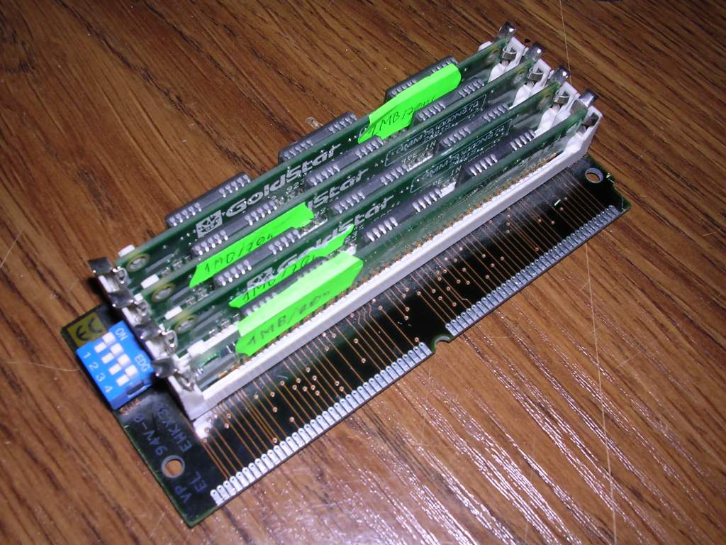
| Later boards used SIPP modules, 30-pin modules with pins. SIPPs have been quickly replaced by SIMMs, which were more comfortable to install and remove - no more bent pins. Most 2 and 386 ATs use 30-pin SIMM modules. Talking about capacity, you will mostly find these: - 256kB - 1MB - 4MB (rare!) 30-pin SIMMs should be installed in pairs (286, 386SX) or, more frequently (386, 486) four modules at once. Most mainboards have a BANK 0 marking and memory should be filled from this bank. If there's BANK 1 and 2, start from 1. |
 A board with DIP and SIPP memory sockets |
These SIMMs can be found in the following speeds: 50, 60, 70 and 80ns (100ns are
rare, you may find them in some early Macs). Usually it's not a problem until
you don't mix them or use 50ns modules in a board which doesn't like them.
Geenrally, avoid using 50ns modules it you are not sure they will go.
In fact, after soldering pins to SIMM you will get SIPP module ready to be
installed in a board. Better way to insert SIMM stick to SIPP connector is to
insert some unsoldered SIMM socket directly into SIPP socket. In most cases
(connection quality) such combination will work properly, but inserted socket
should be secured with some glue.
| In PS/2 architecture IBM introduced 72-pin SIMM modules. These
modules are present in some 486 mainboards, rare 386 and most Pentium
mainboards. They should be installed in pairs, but some rare mainboards have
capability of running on a single SIMM. Their capabilities are following: - 4MB - 8MB - 16MB - 32MB - 64MB, 128MB, 256MB - very rare. Their timings are usually 60 or 70ns, 50 and 80ns are rare. But more important is the techonlogy used to get data from or write to SIMM. There are two such technologies and modules should be used in a borad which supports it: |
 Some mainboards may have slots for both 30 and 72-pin SIMM modules. |
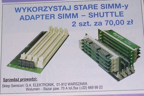
 RAM converter which allows to use 4 30-pin SIMMs as one 72-pin SIMM |
- FPM - the "classical" techonlogy used in earlier DRAM modules. RAM chip
can use pre-programmed location for many reads/writes. Early boards with 72-pin
SIMMs and e.g. 386 processor use it. - EDO - most 72-pin SIMMs use EDO techonlogy. In EDO you can read chip's data while stuffing the next address into it. This makes processing a little faster. Sometimes you may find converters which allow to use 4 30-pin SIMM as one 72-pin SIMM (advertisement for one from 1995). These converters have been made for these rare computers which can support single-simm operation. You will find them in for example IBM PS/2 machines. They don't support EDO so avoid using them in computers better than 486 as they may slow the system down. |
In later Pentium mainboards DIMM modules became popular. Chips
used in them are called SDRAM. They are clocked at 66MHz, 100MHz or 133MHz. It
is important to set the computer's bus clock to the value lower or equal to
module's value. Smallest DIMMs are 32MB (16MB are very rare, made usually for
printers), the biggest may be even 1GB.
And now something completely different: In late 1990s, Cyrix manufactured their
own CPU and AT mainboard which used DIMM modules with... EDO chips. These
modules are incompatible with other DIMMs, so only Cyrix-specific mainboard can
use these modules.
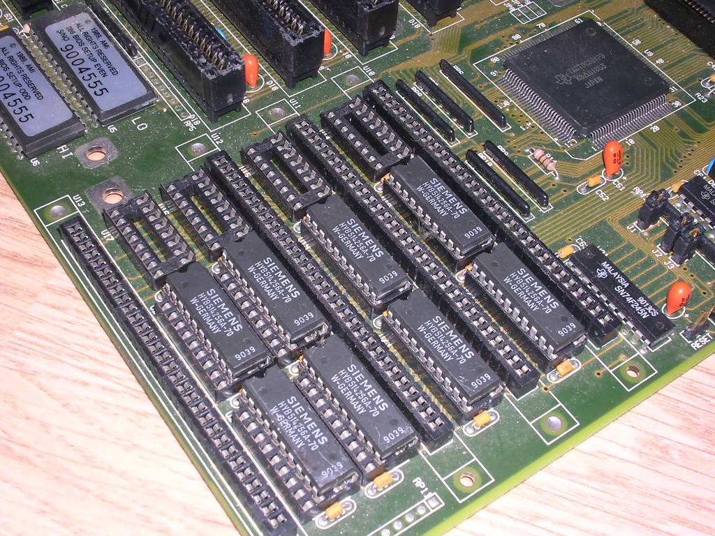
| Now about cache. Cache is needed only in 386 or later processors,
in which it is installed on a mainboard in DIP sockets and then configured as in
manual. You usually find the following cache chips: - 8Kx8 - 16Kx8 - 32Kx8 - 64Kx8 These cache chips should be installed as shown in mainboards manual or as is printed in the PCB. There is a quite big diversity in cache alignments and possible combinations, but you usually need to install main cache (e.g. 128kB: four 32Kx8 chips) and the special cache chip called Tag RAM which serves as a "table of contents". For 128kB (and 256kB) it will be usually 32 or 64Kx8. For 32 and 64kB it's usually 8 or 16Kx8. |
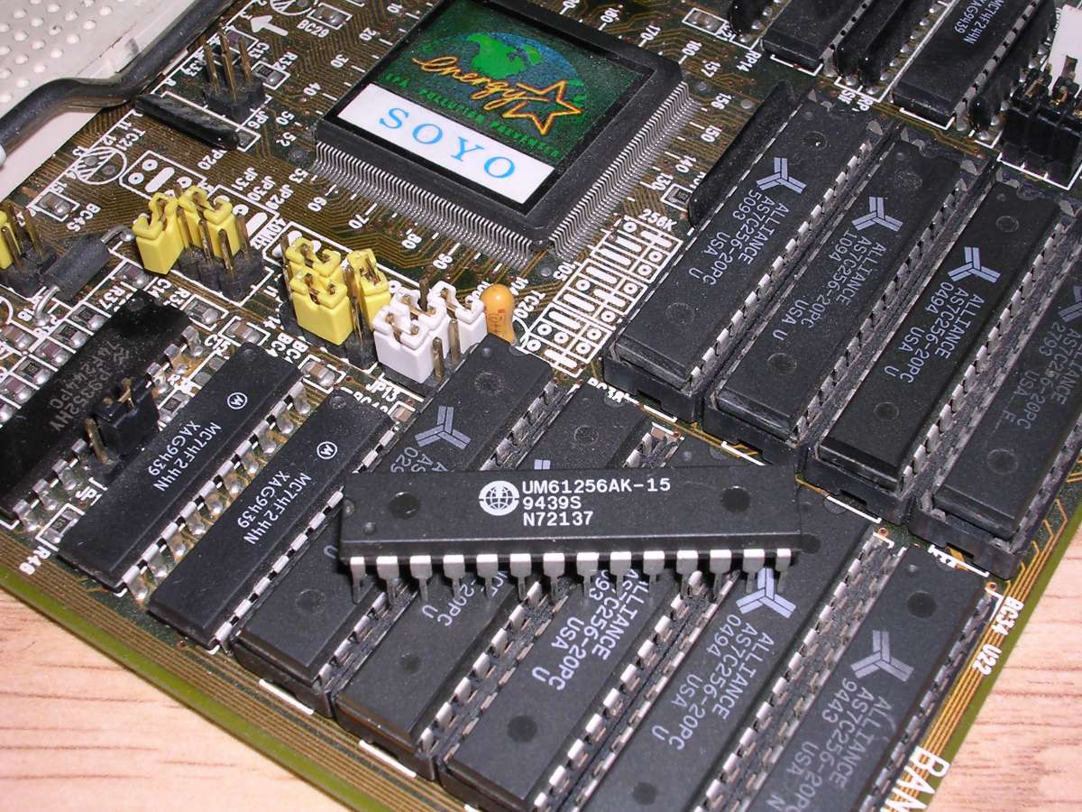 Cache chip |
Some poor 486 mainboards have a dummy cache. Yes, the chips are soldered on a mainboard, but the mainboard has no cache visible to the CPU. And these chips are no cache at all. What these chips are? I have no idea, but you can see such mainboard here. My unit has dummy Tag RAM and surface-mount "chips".
In later mainboards such as Pentium, you can find a L2 cache slot for a special cache called "Cache On a Stick" (COASt). These cards were quite rare. Sometimes OS doesn't know how to use it, so after installing a cache module you may find your Windows 98 is freezing.
For XTs and 286, you can use Check It Pro. It has quite nice
memory testing tool.
For 386 and later (with at least 2MB of RAM) you can safely use
Memtest86+, but not all versions. Be aware
that the latest ones may hang, not load or behave strangely in old computers. If
on your 386 Memtest doesn't boot, try version 4.10 - I've found that later ones
behave erratically on 4MB mainboards. If you have 2MB, you can try version 2.11,
but it is quite picky.
If you plan to diagnose an old PC, make a bootable floppy with Memtest.
7. Floppy disks and drives
There are two forms of floppy disks: 5.25" and 3.5". When formatted with
typical DOS format, their capacity is following:
- For 3.5" disk, Double Density (DD): 720kB
- For 3.5" disk, High Density (HD): 1.44MB (1440kB)
- For 5.25" disk, double density: 360kB
- For 5.25" disk, High density: 1.2MB
Most XT computers support only double density disks and drives. Generally you
can use a high-density drive in such XT computer, but it won't read not write
high-density disks at all and if such disk will be inserted, it will throw
error. To use high-density disks in XT, you should have a special controller
card, usually with its own BIOS.
5.25" disks have no differendes between HD and DD. 3.5" HD disks have a hole
opposite to write-protection tab.
Before formatting a high-density disk as double-density you should know that
here works the same rule as with old Mac disks. Lower density drive has weaker
heads than high density. It means that:
a. Lower density drive will usually read lower density disk made on high-density
drive properly.
b. Lower density drive will not reliably overwrite nor erase data written by
high-density drive
c. High-density drive will usually properly read lower-density disk
d. High-density drive will write to lower density disks, but in most cases see
point b.
So before converting a HD disk to DD you should clean it magnetically by
demagnetizing it before formatting. Demagnetize it entirely using AC
demganetization tool, cover a hole and format it DD. In Windows 9x or DOS you
can format DD disk in HD drive by following command:
format A: /F:720
for 3.5" disk in drive A:
format A: /F:360 for
5.25" disk in drive A:
Floppy disk drives are connected to PC using ribbon cables. Ribbon cable for floppy drive should have a twist on lines 10-16. This twist allows to change Drive Enable and Motor Enable lines for drives A and B, so drive A should be installed AFTER the twist and B BEFORE the twist. Both drives should be configured by Drive Select (DS) jumpers as Drive 1 (they're usually counted from 0: DS0, DS1, DS2, DS3). See below:
[Controller]====||==|=======X=======||==|
B 5.25"
Twist A 5.25"
B 3.5"
A 3.5"
Some early XTs don't use such twist, they require Drive Select
jumpers to be configured as 0 (for drive A) and 1 (for drive B).
ALWAYS MAKE DISK IMAGES. They are handy to use, transfer, extract and
analyse, they hold both files and their metadata such as modification dates or
media defects. Write-protect disks before copying until you know what you want
to do. Avoid making images using Windows 95, try to use DOS until you're imaging
DMF disk. Avoid Windows XP or newer systems as their floppy disk driver is so poor that
it won't read any slightly unreadable disk. Its error support is "one failure =
a whole disk is bad".
For DOS, you can make images using a tool supplied with Norton Commander. This
tool is made to copy disks, it has option to copy disks to image file.
Theoretically you can also use RawRead, but it may fail at the first damaged
sector.
For Unix/Linux, dd or ddrescue works well.
Do not use USB floppy drives for it as they are so poor in quality thet they may
not even read the disk. Forget about reading DMF, XDF or double-density disks
with USB drive. They may only damage the disk.
If you know what you're doing, you can try to recover all useful data from bad
sectors (if you know they are bad, and not are result of e.g. copy protection
scheme) using for example Norton Disk Doctor. It may work or it may fail a whole
disk, so be careful.
After you have a disk image, you can explore it using some programs. For Windows
you can go with shareware WinImage, for Linux you just can even mount it.
If you plan to archive IBM XDF disk, try
SAVEDSKF.
It depends what type of image it is. Look at it, try to open it
with WinImage for example. If it opens, or looks like a normal floppy disk, you
can use RaWrite to write it on
a disk. Such images have IMA, IMG or DSK extension.
IMZ are the same IMA files, but zipped. WinImage tried to introduce this format
some years ago.
DSK files may be the same as IMA/IMG, but not always. IBM made their own DSK
format, which covers all the strange PC IBM formats such as XDF (formatting
high-density 3,5" disks to 1.88MB). The tool for handling such DSK images is
called LOADDSKF to
restore floppies. It should be ran from pure DOS.
CFI - These files are disk images which were distributed by Amstrad and can be
written with FDCOPY tool. You can find it
here.
DDI -
DiskDupe files.
VFD - Readably by VMWare and VFD
DMF disk image files are usually supported only in Windows. You can use WinImage
for them.
TD0 can be written only with Sydex TeleDisk software.
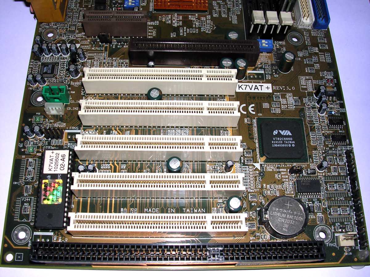
10. What slots I can find inside a PC?
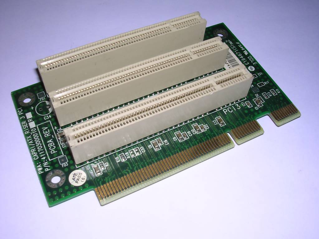
| Own riser slots Some mainboards installed in small casings have one slot, usually in the middle, which should have a riser card on it. Riser card has one or more ISA (sometimes PCI, or both, there are some VLB riser cards too) slots and is used to install cards in parallel to mainboard. If you have a mainboard but no riser, sometimes just any compatible ISA riser works because the riser slot is ISA with all connectors used. Sometimes it indeed is ISA, but without notch, pins in the notch are used for higher power connection. Other mainboards have their own proprietary riser formats. You will find incompatible risers in computers which have been entirely made by one manufacturer (such as IBM, Dell, Siemens, etc.). |
 |
8 and 16-bit ISA slots
Typical ISA slots, 8 or 16bit. In XTs, 2, 3 or 486 computers they are primary
slots for most cards. In later models usually PCI is used, so ISA is used e.g.
for a sound card.
In 286 and later models ISA became expanded to 16-bit.
In some industrial PCs, 16-bit ISA slot is made as 3-row pin header. 2 outside
rows roughly correspond to 8-bit ISA slot connectors.
Most ISA cards are configurd using jumpers, but some have different levels of
Plug-and-play capability. Some ISA cards, especially network cards, require
specialized software to change their configuration.
Usually any card can work in any slot. The exception is first, third or last
slot in some early XTs as they are dedicated for connecting special expansion
chassis.
VLB
In some 486 mainboards you will find one, two or three ISA slots expanded with
VLB slots - with more densely packed pins. These slots expanded ISA to 32bits
and it's faster, but has significant downsides. First, it works with bus speed,
so faster CPU may cause that the slower card won't work with it. Second problem
was if more cards were installed - such combination in most mainboards won't
work as VLB is just direct expansion of 486's address bus. Another problem was
physical combination of 3 slots one after another (ISA8, ISA16, VLB) which
caused contact problems.
Because VLB is just 486 address bus, if more cards are installed one card should
take care of maintaining which card does what in which moment. In this
situation, card with bus mastering should be inserted in MASTER slot.
You will find graphics cards and hard disk controllers made for VLB. It usually
is present in 486 mainboards and is rare in later ones.
PCI
PCI bus started to show in Pentium mainboards, bus some rare 486 have it. You
can find nearly any type of card for PCI: Graphics card, connectivity, sound,
hard disk or port controllers, multimedia cards, even 3D accelerators which have
pass-through capability. The first PCI has 32 bits and works at 33MHz, so
contrary to VLB it's independent of bus clock. There is also a faster PCI 2.x
version with two notches (64bit), not one, or a notch on the other side of slot
(32bit). Some cards are universal and can work in both slots, these cards have
two notches.
PCI cards have more capabilities than ISA cards but their base capabilities They
may also contain ROM which can be started at boot. Most PCI cards are
jumper-free or have some really advanced settings with jumpers - they are
configured using Plug-and-play satndard.
AGP
When graphics cards became faster and faster, 32-bit PCI started to be a limit.
In 1997 AGP slot was introduced. You can find it as a single slot, in some
Pentium mainboards (since ca. 1997) or later in Pentium II or III mainboards, where it's present
in 99% cases. AGP works at 33 (rare) or 66MHz with different multipliers (x1,
x2, x4, x8) to transfer data faster. It is important to use graphics card with
slot which supports it as then it will go with a full speed.
 Top to bottom: AMR, AGP, PCI, VLB |
For AGP you will find only graphics cards. From the simplest ones with 4MB of
RAM (some are using the same chips as PCI cards), to complex, accelerated cards with hundreds of megabytes in DDR memory
and even computing capabilities. AGP has been replaced by faster version
of PCI (PCIe - PCI Express and PCI-X). Because AGP cards have quite dense contacts which may easily slide off or disconnect during mechanical moving, there may be a "lock" on a slot which holds the card in place. It is made as a sliding part or round pin on spring. Some AGP slots have a high-power smaller slot in front of AGP slot (sometimes called AGP Pro) to provide additional power for graphics chip, but it's usually present only in some Macs or few high-end CAD workstations. |
One more thing: In the time of Pentium IV, not all chipsets still natively support AGP. For example ASRock used these chipsets in their mainboards. Then they made a special interface partially compatible with AGP called AGI. It is compatible with only a few dozens of graphics cards, so if you can't use mainboard with one AGP card, consult your manual to check is the AGP slot a real AGP, or does it have some "compatibility list". Similar tricks have been made by Epox and Biostar
|
|
EISA ISA was slow but it had one more problem: Every card had to be configured using jumpers. Memory address, IRQ number, DMA channel, some on-board settings had to be configured by placing jumpers on many pin headers. EISA was a response to this problem. It was still running at 8.33MHz, but it was 32-bit. Most slots are backwards-compatible with ISA, EISA cards have just longer edge connector going deeper into slot. How to configure card without jumpers? Every mainboard has EISA controller, configurable using dedicated program (usually booted from DOS floppy). The program can read configuration files (usually text or some firmware) and present options to user. After user configures options, they are written to EISA card corresponding to file. The card stores settings and applies them on boot. This mechanism is incompatible with Plug-and-play and Windows 95. It requires specific configuration file for each EISA card and proprietary program for mainboard. |
You may find some cards with bloth ISA and EISA slots, especially multimedia or
network cards. These cards can be flipped and installed in another slot,
replacing the bracket.
You will find EISA slots on professional machines, usually with 486 processor.
Cards for EISA may be specialized (e.g. multi serial port cards, data
acquisition), but they are quite rare.
MCA
MCA slots are used in some IBM PS/2 line computers. MCA is 32-bit bus (16bit in
compatibility mode) working at 10MHz. It hasn't got much popularity because it
was purely proprietary, made and licensed by IBM, so many computer manufacturers
just used ISA, EISA or VLB.
MCA has some unusual capabilities. MCA graphics card slot has analog output
which can lead to computer's monitor output. Mostg cards have a big plastic
expansion to stably fit into computer casing.
MCA used another approach of jumperless configuration. Every card has a 16-bit
ID which is read by BIOS and checked for known cards list. Then the card can be
configured in BIOS. It is easy but inserting a brand new card not known by older
BIOS caused the computer not to start. For MCA PS/2 computers IBM released BIOS
updates frequently.
| ACR/AMR A small slot (in early mainboards it was made using PCI slot soldered backwards and shifted a little) for sound card and modem I/O devices. The slot is made the way that CPU controls the device directly, so the device can be cheaper by cost of system performance. There are usually 3 types of slots: - AMR - Audio Modem Riser - Appeared along with Pentium III mainboards, supported usually MC97 modems or AC97 sound cards. - ACR - Advanced Communications Riser - Replaced AMR, sometimes used reversed PCI slot and allows 46-pin AMR cards to be installed. There are very rare wireless networking cards for it. After ACR cards started to support EEPROM or advanced I/O it was replaced by already present PCI. - CNR - Communication and Network Riser - alternative to ACR/AMR, appeared in some Pentium 4 mainborads. While AMR had 46 pin slots, CNR has 60 pins. CNR cards are fully plug-and-play. |
|
11. What expansion cards do I need for my...
...XT?
- Graphics card - you can usually have CGA which has graphics capabilities
but poor text mode, MDA which has good text mode but no graphics at all or
Hercules (HGC) with good text mode and monochrome graphics. XTs can use
8-bit ISA VGA cards.
- Floppy disk controller - You need something to boot from
- Serial/parallel port controller
- Hard disk controller
- Optionally: RTC card, to keep date and time.
Remember that RTC cards and hard disk controllers have their own ROM which, before
booting DOS, sets up the system clock and allows to boot from hard disk (XT's
BIOS doesn't know hard disks). If a floppy disk controller card has its ROM it
may be possible that it supports 1.2MB (5.25") or 1.44MB (3.5") floppy disks,
not only 360kB (5.25) or 720kB (3.5") supportde by typical XT BIOS.
...AT 286/386?
- Graphics card. Here you can find a variety of VGA cards for 16-bit ISA.
- Floppy/hard disk controller. Most AT BIOSes understand hard disks more
or less, so you can use a typical non-ROM HDD controller for MFM or IDE drive.
- Serial/parallel port controller.
If there is one controller for floppy, hard disk and serial/parallel ports
(sometimes game port), it's sometimes called "Super I/O" card.
...486?
- If you want to make it display, use a good, graphics card, maybe even
with VLB.
- Use some Super I/O card definitely for ports, FDD and hard disk.
- Sound cards start to be useful in 486s.
- CD-ROM card maybe?
...Pentium?
Most things are usually built-in the mainboard here. You usually need:
- Graphics card. Use a nice one in PCI slot (e.g. S3 ViRGE 64, avoid
Tridents as they are difficult to configure) or even some 4MB AGP one if your
mainboard has AGP slot. If you
want 3D acceleration you can think about external accelerator card (e.g. 3DFx
Voodoo) or just accelerated graphics card.
- Sound card - In Pentium mainboards you stille have ISA slots, so if you
use ISA card, you may have sound even in DOS games. In Windows some ISA sound
cards may saupply additional IDE channel for CD-ROM, but it can be used not only
for CD-ROM but for slower hard disk drives too.
- Network card - they start to be useful in Pentiums, especially in
Windows-based ones.
RTC Solutions for PC XT...
This is worth noting as there are many solutions for it. The original XT had
no battery-kept Real-time clock. Generally these clocks in mainboards became
widespread in 286, most 8086 and 8088 have no RTC. So different manufacturers
used different approaches to attach the RTC. RTC is not a device which requires
constant data transmission - it is occassionally set and then it operates from
battery, every system boot-up it needs to be accessed to acquire current date
and time and that's all. So different approaches were used. There were RTC
modules hooked between CPU and mainboard in small PCBs, there were modules for
ISA slot, even serial or parallel port. Most RTCs are in ISA I/O boards usually
containing not only RTC, but also a serial/parallel port controllers, sometimes
floppy drive controller.
Remember that not all "Y2K-compliance boards" have RTCs ready for XT. First, the
ROM may be incompatible. Second, the memory location may be not suitable for XT.
Third, the ROM software may miss DOS clock in XT.
If the board contains ROM, it may happen that the ROM boots the system and sets
the clock. However in most cases the cheap board has no ROM and the clock has to
be operated using software. This RTC, even when runs, will usually not be
present as typical RTC and diagnostic software may not report the computer as
equipped with RTC.
The RTC pops in memory map somewhere, usually about 0x200-0x300h. Then by using
specific driver it can be set usually from current DOS clock (this is settable
with commands "date" and "time") and retrieved to DOS clock every boot. However
different RTCs have different drivers.
The floppy disk supplied here contains various drivers.
Especially in XT it is important to have the fastest driver to make the computer
boot quickly. Start with CLOCK.COM as it's slow, but has quite large informative
capabilities and chips/memory locations support - it is possible to retrieve
information where the clock is in memory and which chip does it use. If you got
it and it operates (assuming battery power is suplied), you should try a faster
driver to make system boot faster.
Serial and parallel ports and their brackets
Most of PCs have some serial and parallel ports. Usually we have a single
parallel port and two or one serial. In most 286s and later, there are boards
with two serial ports. In XTs, there may be a single serial port or a board
which has missing chips for seocnd serial, for future upgrade. If two parallel
ports are present, usually this is caused by video board which (MDA or Hercules
usually) has its own parallel port, and multi I/O board which also has.
To upgrade the single-serial board to dual-serial, you usually need 4 things:
- Serial chip - this is a must-go, the chip which makes RS232 signals,
usually 8250 (XTs, up to 9600baud) or 16450 (pin-compatible but faster) or 16550
(faster, in many cases compatible, pinouts
here)
- Two, or in some cases four (two of each type), driver chips which
interface with RS232 voltages directly: MC1488 and MC1489, or 75188 and 75199.
Each of these chips have four drivers/receivers. It means that with a simplified
serial port, containing of 3 outputs (Transmit, DTR, RtS) and 4 inputs (Receive,
DCD, DSR, CtS) it's OK. Additional chip is needed if additional lines such as
near-standard RI input are present - in some cases it's only MC1489/75189.
- The proper bracket with connector. If you unfortunately have this
controller board with single-line connector, you have to use ohmmeter and "blow"
the line to MC148x and further to controller chip to know which pin goes where.
Just open datasheets of MC1488/89 and your serial chip. If you have 10-pin
connector (2x5) or 26-pin (2x13), it may be better.
There are two main types of connections, and in them pin 10/pin 26 is just absent, not connected. First is 1:1, means that if you crimp 10-pin connector to 9-pin ribbon leaving pin 10 absent and crimp the other end of ribbon to 9-pin one starting from pin 1, it will be OK. Because pin-based board connectors count this way:
1 3 5 ...
2 4 6 ...
And DB goes this way:
1 2 3 4 5
6 7 8 9
the numbering is not consistent with pins. To illustrate this, instead of crimping connector, let's try to solder the ribbon to DB9 connector. To reflect crimping, you have to solder ribbon's wire 1 to connector's pin 1, then wire 2 to pin 6, wire 3 to pin 2, wire 4 to pin 7 etc. However, some connections go directly, means wires 1,2,3 etc. go to pins 1,2,3 od DB connector. You have to distinguish your connector.
To check does it work well, you can run port diagnostics (this bootable disk contains it) with special loopback plugs. The plugs have been shown below and for quickest tests the best way is to have one parallel, two DB9 serial plugs and DB9-25 converter or DB25 loopback plug:
Serial, 9 pin 1 - 6 - 9 - 4 2 -3 7 - 8 |
Serial, 25-pin 6 - 8 - 20 - 22 2 - 3 4 - 5 |
Parallel, 25-pin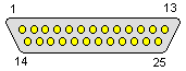 11 - 17 10 - 16 12 - 14 13 - 1 2 - 15 |
12. I have no idea how to configure my hardware - Where can I find help?
The most popular source about PC components is TotalHardware
'99, found in lots of mirrors over the Internet. For example
here. There are few versions of
it:
- "Full" TH99, has "Jumper settings for 18655 devices" and contains
pictures.
- "Lite" TH99 has "Jumper settings for 18655 devices" but doesn't contain
pictures.
- Early version with only 14K or so, not 18.
The history of this wonderful set of manuals is not much known. The images are
identical as in the Micro House Technical Library. Micro House published their
hardware datasheets on CD-ROMs in 1990s, but in 1999 they have been acquired by
EarthWeb. In 2001 they stopped offering support on CD-ROMs.
TotalHardware is probably a dump of contents form these CD-ROMs in HTML format (my
one CD-ROM
from Micro House contains documentation in their proprietary format). In the
history the name "A. Haning" (proof)
has shown in 2002, when he was offering two versions: Lite and full, probably
commercial. In his sites, mr. Haning writes about "Original TH99 CD-ROMs". Are
they MicroHouse CD-ROMs? It is not known.
If you are looking for hard disks or controllers info, see PC-DISK (archived copy), it's like TH99 for hard disks, and the source of information is probably the same as in TH99. There are only more information about disks.
If you like to read about components, visit Red Hill Technology site. They have a nice descriptions of old computer parts, strange devices or drives.
For pinouts, go to pinouts.ru. They have pinouts of most popular connectors, sometimes with extensive descriptions.
| MFM, RLL Historically, the first hard disks in PCs. The proper name of this interface is "ST506" or "ST412" interface, taken from first disks with this connection. They are the famous disks "connected with two ribbon cables" to the controller. The wider cable is control cable which directs drive, the smaller one is data cable for data transfer. Data signals are not processed, these are magnetic flux changex read from disk, it's the controller's job to decode them to data understandable by PC. MFM disks usually require low-level formatting before using. To low-level format, you should boot DOS and run the program from controller's ROM by running debug program and typing e.g. g=c800:5 (where c800 is controller's ROM address). Before powering the system down you should park heads using a special program. |
|
If you want to use more than one disk, you should connect two disks with two separate data cables, but with one (no interleave) wider, control cable. Just crimp another connector on it. Next, you have to set proper IDs on disks and terminate the last one.
RLL was the next step in this technology. Some controllers may use
RLL modulation instead of MFM, which allows to store about 50% more data on a
hard disk (by adding half to number of sectors per track). For example 20MB disk
may store 30MB.
Theoretically it is possible to use every MFM hard disk as RLL, but practically
there are some good-quality RLL-certified drives. MFM disks may become
unreliable when formatted with RLL.
In these disks an interleave is a very important factor
affecting performance. To understand the interleave you should know how the
operating system reads and writes to disk. Generally, the system positions the
head above desired track and reads/writes it, processing one sector a time. So
after writing sector 1, the system must prepare the sector 2 and send it to disk
when the head will be above sector 2 (disk is constantly spinning). During read,
decoding of the sector takes some time and when the controller is ready to
receive the next sector, it must also wait before the head will be above it.
The problem is that when you place the sectors sequentially in a track
(1,2,3,4,5...), the disk spins too fast for the controller and the next sector
"runs away" before it's needed and the head is above unneeded sector. So the
controller must wait another disc revolution to access the next sector.
The solution is placing the sectors in the interleave, which means that, for
example, the next sectors are every third sectors in the track. It means that
after reading sector 1 system processes it, and in this time the disk spins two
sectors, the head reads fourth sector which is logically sector 2, and so on. It
improves performance.
The interleave can be automatically detected by some controller's BIOSes, it is
dependent on the disk and controller model. Interleave is set during low-level
formatting of MFM disk. Remember that tuning interleave is usually
destructive as it formats the beginning tracks of the disk to detect the
speed and find the best interleave.
ESDI (PS/2)
ESDI (Enhanced Small Disk Interface) use the same cabling as ST506, but the
interface is different. Modulating and demodulating data from signals is now
done by a hard disk's electronics and 10, 15 or 20MBit/s speed can be used. ESDI
drives were more expensive than ST506, later they became significantly larger
(even over 100MB), so they are more rare today. The exception is a specialized
ESDI-like single edge connector present in IBM PS/2 computers sometimes called
DBA (Direct Bus Attachment). In this connector both ESDI connectors and power
supply are integrated. ESDI disks, as MFM, usually need to be formatted by
controller, but case in which controller reads newly connected disk are more
frequent than in MFM.
Seagate-SCSI
Quite rare SCSI-like format used in some early Seagate hard disks for early PC
XTs (these disks have usually 60-100MB). It looks like a SCSI, 50-pin ribbon
cable, but is totally incompatible with standard SCSI. Proprietary hard disks
are used with proprietary controllers, which have their own ROMs to boot a PC
from the drive.
Avoid using these devices as they have no error correction at all.
If there is a damaged sector, the hard disk will read it without complying, and
you will find the problem viewing your damaged data.
These devices can be low-level formatted from the controller.
IDE-XT
IDE is a very misleading shortcut. It may be "Integrated drive electronics" or
"Inteligent drive electronics". The proper name is ATA - AT Attachment, as the
ATA signals in 40-pin cable is just buffered and selected expansion of AT ISA
bus.
But we are talking about XT. IDE-XT, known as XTA or "XT-IDE" (not to be
confused with XT IDE cards offered today) is ATA expansion trimmed down for PC
XT.
The most important thing here is that the main tasks made in MFM or ESDI by
controller is now done by drive's electronics and signals coming to drive are
using it similarly as other ISA card. The XT drive is usually incompatible with
ATA, only some drives are compatible both with ATA and XTA.
Programmatically, XTA hard disk has 4 registers pretending to be an XT hard
drive controller.
AT hard disks usually won't work with XT hard disk controller cards (to be
specific the controller card is not controller card, because controller is in
the drive and card is only an interface, but it's traditionally called
controller), because ATA disks are working in 16-bit mode while XT is 8-bit. In
most cases they don't need low-level format. The jumper configuration of
XT IDE disks is the same as AT IDE, except there may be some additional jumpers.
WARNING: These disks are not protected against ribbon cable mistakes. If you
insert the cable wrong way, you may destroy the drive electronics!
IDE/ATA
A typical IDE ATA (later known as PATA) hard disk. It can be from 40MB to 500GB
or sometimes bigger. ATA allows to connect not only hard disks, but also CD-ROM
drives and some rare tape drives. Drives don't need low level formatting and
low-level formatting them from some BIOS controller may damage them. One
ATA channel (connector) supports up to 2 drives in master-slave configuration.
This bus is the easiest to configure as only jumper configuration is needed.
The configuration consists of at least two jumpers: Is the disk master (if
jumper installed) and is the slave disk present (closed in master). There may be
of course other jumpers or activity LED output.
Later ATA drives are made for higther speed transfers, up to 133MB/s. These fast
ATA drives require special dense ribbon cable (with 80 conductors - 40 for
signals, 40 for shielding) with specific plugs for master and slave drives.
If your BIOS has option to low-level format hard disk and IDE drive is
connected, don't use this option. In the best case hard disk will pretend that
it's formatted (while no data will be written), in the worst the service tracks
mayh be erased and drive will be irrecoverably damaged.
SCSI
SCSI (Small Computer System Interface or Shugart Computer System interface) is
an universal interface for connecting hard disks, tape drives, optical drives or
even scanners. Most SCSI controllers have their own ROM with a special loader
program which detects hard disks and appends them to system. SCSI disks usually
don't need low-level formatting and older SCSI disks can be at least detected in
newer systems only if their connectors are compatible.
In old PCs you can mostly find 4 types of SCSI connectors:
- 50-pin ribbon cable
- High-density ribbon cable - usually in mid-90s hardware, allowing to get
even 320MB/s, used in servers.
- High-density external cable (two variations of this exist)
- External DB50 connector (rare)
A nice guide of SCSI standards and connectors can be found on
SCSI4Me Site.
SCSI devices can be internal or external and are daisy-chained. To add a device
to the chain you must configure two things:
1. Device's ID, by using jumpers representing ID number's bits.
2. Termination, which should be made on the last device, if not with a device's
terminators, a special external termination block may be used.
SCSI devices have an option for low-level formatting but it's usually not needed
and in some rare cases harmful to drive.
14. My hard disk is not fully visible!
There are few causes of it. Let's see how the disk is visible in
system:
The hard disk has usually 3 parameters about its geometry: Cylinders, heads and
sectors per track count.
- Heads count is a number of heads, usually there are 2 heads
for each platter.
- Cylinders cout is a number of tracks ("rings") on a
side of platter.
- Sectors/track count is the number of sectors per track. The
sector size is in 99% cases 512 bytes. There are some very rare disks with 256
sectors.
So Cylinders*heads*sectors*512 = size of disk in bytes.
Now: Generally adding more heads is adding more platters, so the disk will be
larger, more noisy and will use more power. Larger disks rarely have more
platters - they just have more tracks (cylinders) or sectors in a track. All
these parameters must be in BIOS to properly detect drive.
As drives grown, it was needed to store more information and sectors/track cound
became too large. Then disks got a translation device built-in. Generally it
works by pretending that the drive has more for example heads than it really has
(for example two-platter disks reports 16 heads), and when the data is
addressed, the physical location is achieved internally by drive. This
translation is sometimes called "Large mode" or "LBA mode".
Older versions of DOS can have partition limitations on 30MB.
This is a purely file-system problem and can be fixed by using more partitions
or another version of DOS.
The first cause of a smaller size is a bad geometry entered to BIOS setup. If
proper geometry cannot be entered because, for example there are more than 1024
sectors per track on disk and Setup doesn't accept it, it means that it cannot
support the drive. You can try to use another mode (LBA, LARGE), or try to
auto-detect disk to skip user input.
Sometimes you can enter larger numbers, but the disk pretends like it has only
1024 sectors per track - it means that BIOS setup can accept this number, but
the controller routine can't. You will usually see this limitation as 504MB
disk limit.
Phoenix BIOS version 4.03 and some clones (usually from 1996-97) have a
problematic way of storing cylinders count - they are written using 12 bits
being 4095 maximum. So the largest hard disk will be ca. 2,1GB. The only
way here is to upgrade BIOS or use Disk management software. The problem
*seemed* to be fixed in 4.04 release of BIOS and indeed, it was fixed, but not
at BIOS Setup level, so disks larger than 3.2GB could hang the setup.
Some mainboards have 4.2GB limit. This is a limit of LARGE mode which
works by virtually doubling heads count and halving cylinders count to get some
safe 1024-cylinder level. But it doesn't run ad infinitem, maximum number of
heads multiplied this way is 15. Any drives larger won't be fully detected.
Other BIOSes start from 15 heads, this makes a 7.9GB limit.
Most old Pentium (and some later) mainboards have 8GB (or 8.4GB) disk
limitation. This is because in some LBA there is a limit to 255 heads and 63
sectors/track. So we have 1024*255*63*512 = 8422686720 = 8032MB at maximum. If
you encountered this problem, try to auto-detect the drive, it may be detected
with strange geometry and then become visible to system with its full size.
You can also find 32GB (or 33.8, 34GB) limitation because X*16*63 geometry
overflows. There is also a 137GB limit.
Some disks have a jumper which limits their size to 4, 8 or 32GB.
This is a special jumper for compujters which can't access these disks at all,
but it unconditionally limits the size.
If you want to read more see these links for
2GB limitation,
4GB limitation,
8.4GB limitation and
3.2GB limitation. These are old documents from manufacturer of ATA
controllers.
| To bypass these limits you can: - Update BIOS to a newer version (if you are sure it will work - never update BIOS if you don't know what you're doing!), - Install a special card with its own disk BIOS - if the controller supports bigger disks and only BIOS is the problem, this card will fix it. - Install a dedicated hard drive controller which has its own controller chip and BIOS - Use a DiskManager program - it creates a partition with some acceptable size, boots DOS from there and loads a driver. The driver overwrites BIOS in disk access so the second partition, covering the lacking disk space, may be used. The main problem with this solution is that if you boot from pure DOS floppy you won't have a full access to the hard drive. DiskManager will be useful if you want to use 3 or more MFM disks too (described here) in XT. In AT, use additional driver. |
|
So you want to use DiskManager?
Generally, there are some OEM versions of DiskManager which work when you supply
them drive geometry. To get the disk formatted properly, it is important to use
the proper version of DM. Newest DiskManager won't format old MFM drive.
For the old DOS versions and MFM disks, DiskManager version 3.2
or 4.0 will be good in most cases. Sometimes 6.x or 7.x may work if Windows is present. Windows 95
started to be supported from version 7.
For Windows 95, try version 9.
15. Serial and parallel data transfer cables
| If you have a PC, let's talk about cables which will be used for
such transfer. Generally there are two types of cables: Parallel and serial. Parallel cable for data transfer can be made using this schematic. It will work both with ZIP as well as with Norton Commander connectivity tool, Windows 9x "Direct cable connection" (remember to put both computers in the same workgroup before or they won't see each other!) or Norton Ghost 2003 if you want to clone hard disks through parallel port. It can be made or bought. The biggest problem is that it won't work in all computers. Generally many XTs have unidirectional parallel port, which means that it may only transmit data (to a printer), not receive. In this condition file transfer using parallel port is not easily possible. But XTs may have serial ports. They can both transmit and receive data. It's slower but may work. Remember that in XTs you may get problems (connection errors) if you use high speeds (baud rates), so keep it lower, e.g. 9600 baud (ca. 1.2kB/s) or twice as fast. 115200baud (14,4kB/s) causes errors in most XTs. Serial connection works with ZIP using a null-modem cable. What is a null-modem cable? It is a serial cable in which some lines are swapped. They are swapped such way that if one computer sends data, it is connected to receiving pin on the other computer and vice versa, if one computer requests, the second one receives request and vice versa. Such configuration is called handshake and is described in this page. PCs amy have 9-pin or 25-pin serial ports and if you want to make a convenient, universal cable, you should cover all scenarios of using it. So you should make a cable the following way: [9pin plug]===[25pin plug]======NULLMODEM======[25pin plug]===[9pin plug] |
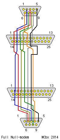 |
Then you can connect this cable both to 25 and to 9pin connectors. Remember only to keep wires between 9 and 25pin plugs short (maximum 15cm) and that nullmodem twist goes only between 25pin connectors. I'm using such cable (made by "Travelling Software") without problems.
16. Transferring hard disk contents to a new PC.
You have an old PC on your desk and you want to get it to useful state. After you made the hardware able to start, you should think about transferring precious files from hard disk to a new PC. By this transfering you will get some old programs you can use in other PCs. Sometimes this software is not accessible anywhere else, so looting contents of an old hard drive may be very useful. Generally, the steps are following:
0. Make the computer able to boot DOS.
1. Boot DOS. Use machine's hard disk or, if it's not bootable, use DOS 6.22 boot
disk (until you're using FAT32).
2. Travel through hard disk directory structure and look for contents you want
to archive. Avoid moving files too much as hard disk may be damaged. You can
test the disk before using something like Norton DiskDoctor.
3. Transfer the files:
- By floppy disks - ARJ becomes useful here. This method is not
recommended because you may transfer large amounts of data using unreliable
floppy disks.
- By parallel port or serial (if your computer has unidirectional parallel
port) cable and
ZIP program. Do not confuse it with ZIP compression program. This program
allows to set up "server" on the PC, so you can transfer data from it to another
PC running DOS, Windows 9x or Windows XP if
UserPort is installed. Remember to configure ZIP properly.
If you can't transfer ZIP using floppy disks (for example damaged proprietary floppy disk drive) but you can boot DOS on the machine, use serial cable and ZIPDUP as explained in documentation. Do not format its hard disk as you will end with unbootable computer.
If you want to preserve DOS, you have to preserve boot block. Boot the DOS you want to preserve, then make a system floppy by formatting it ans typing sys a: (or b:), then put FDisk, Format and Sys (at least) on this disk. Then you can format new hard disks and make them bootable with this DOS by just typing sys c: on the blank hard disk.
If your PC has IDE drive, you can connect it to another PC and just see what is inside or diagnose it with e.g. MHDD.
17. Formatting hard disk and placing new version of DOS
MFM
Boot machine with DOS floppy with DEBUG program. Type DEBUG, then g=c800:5 (if
card's ROM sits in c800, in most cases it is).
Low-level formatting software may start.
If it doesn't, use OnTrack Disk Manager but without
driver for bypassing capacity limits.
After it's low-level formatted, DiskManager will automatically place booted
version of DOS on it. You can replace it with another version of DOS.
If you have a low-level formattred MFM disk, proceed to partition creation.
IDE
These disks don't need low-level formatting and doing it may damage them. Just
configure them in CMOS Setup and you're ready to partition
Partitioning
Boot DOS, run FDISK, Create at least one primary partition and set it active.
This will be a C: drive. You can then create extended partiion with one or more
logical drives (D:, E:, F:...). Changes are irreversible.
Formatting:
Type FORMAT [disk]:, for example FORMAT C:.
If you want to automatically transfer DOS, type FORMAT C: /s
System transferring
Type SYS C: to transfer DOS to the disk. After this operation the
partition will have only essential files to run DOS, no drivers or programs.
If you plan to use DOS 6.22, you can install it on only formatted disk, it will
install itfels with installation program.
Bad sectors in the worst place in the HDD
Sometimes, especially when using MFM drives, you may get bad sectors in the
beginning of disk. In such disk you can't make partitions with FDisk because
FDisk will hang during verification step. In such case use Disk
Manager as it can shift the main partition outside damaged area if
verification fails.
18. Getting the software into PC
Now you want to install some software? OK, here are options:
Floppy disks
They are made on another PC from disk images or loose files. Software sometimes
need installation from original floppy disks. This method requires user
interaction and damaged floppy disks may make the process longer.
|
Serial/parallel cable If you plan to use many PCs, you can prepare a directory with different programs which will be received by cable. It saves lot of time. For example, in my directory I have 3 copies of TAG editor (for CGA, VGA and Hercules graphics cards) installed on VM. |
|
Hard disk transfer
You can also remove a hard disk, record software on it and place it back in a
PC. This solution is limited only to disks which can be used such way, so forget
about filling MFM disks using this method, but it will work with IDE.
19. What essential programs I need for my PC and where to get them?
Usually you need:
- DOS - the newest stand-alone DOS is 6.22. Few years ago China DOS users
ripped DOS from Windows 95 or 98 and released it as DOS 7.10. It is not much
compatible with older DOs software, so you usually need DOS 6.22 or 3.3, 4.x -
if you have access, you can use OEM version of DOS for your hardware. Remember
to include HIMEM.SYS if you have more than 1MB of RAM.
- File manager - here, use Norton Commander or XTree. For powerful 386
with large amounts of RAM (or 286 with 1MB) use version 5.0 or 5.51 (5.51 is a
bit slower). For old XTs, use version 4.0, it is smaller and less
memory-consuming.
- Utilities: For defragmenting hard disk, checking for bad blocks and
general testing, some Norton Utilities is enough. Avoid installation of
"Smart can", batch expanders or similar crapware as it may slow your DOS more.
- Text editors: WordStar, ChiWriter, Microsoft Word for DOS. For editing
text files, you can use Norton Editor or EDIT from MS-DOS disks. Polish users
may prefer TAG.
- Spreadsheet: Quatro Pro or Lotus 1-2-3.
- Games - there are many DOS games available in TOSEC or abandonware
sites.
If you plan to use Windows:
- Windows 3.11 or 3.11 For Workgroups - works best with 386.
- Drivers for your graphics card. WARNING: If you have a non-american
codepage, before installation replace driver's fonts with your system's fonts
(FON files). It usually works, and you still have a non-standard codepage.
- Drivers for network, sound card or other multimedia devices
- Win32s.
It is essential to run some 32-bit applications.
- Spreadsheet: MS Excel 4 or 5, or Lotus 1-2-3 for Windows
- Text Editor: MS Word 6.0 or Lotus AmiPRO 3.0
- Database: MS Access 2.0 or Lotus Approach
- Presentation: MS PowerPoint 4.0 or Lotus Freelance Graphics.
- Other software. If you want Windows 3.11 to look more like 95,
Calmira is your friend.
- If you want to use graphics software, you can use CorelDRAW! 3.0.
- Internet: TCP/IP, MSIE 3.x or early 4.x, maybe Netscape.
If you are using better computer with Windows 95:
- Windows 95, the newer version the better
- Newest patches.
- Internet Explorer. Version 5.5 contains explorer integration
- Office 95 or 97
See this article for more
hints.
20. Year 2000 problem on an old PC
There is no single Year 2000 problem (see the appropriate
FAQ), but many problems have ended with year 2001. For example, every fourth
year is a leap year, except years which divide by 100. Another exception is that
if the year divides by 400, it is not taken as dividable by 100. As in 2000. If
you expect that all BIOS programmers included these rules you're wrong.
Fortunately in 2015 the biggest problem is: Will it work with 2015 (four-digit,
over 1999) year and will it correctly flip dates?
In late 90s there were some programs to
test all possibilities. Today usefulness of these programs is questionable. Just
try to set date in BIOS. Does it work? OK, does it preserve this date?
If it won't let you enter the date, maybe it's just BIOS Setup's fault? Boot DOS
and try to set time form DOS.
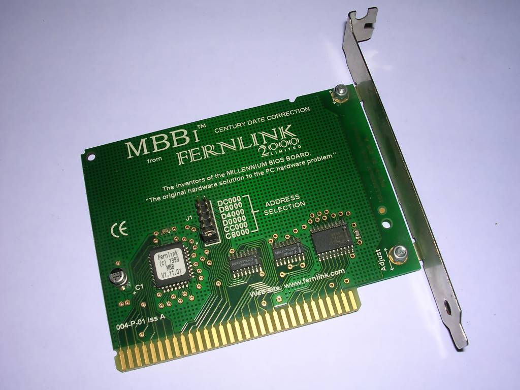
| The problem starts if you totally can't set the date (even in DOS),
it is displayed incorrectly, days don't change etc. The problem may be
in one or more components: - RTC itself - The problem in RTC can be diagnosed with AMI2000. Happens rarely, but only special card with RTC will help. Unfortunately such cards may contain known Dallas DS1287 chip so if you are unlucky it may require rework. - BIOS - Try to find BIOS update, if BIOS is not in ROM. If you really can't find it, there are hardware cards with special, 2000-compatible BIOS which can be installed. - Operating System. Try to change it or update. - Software - update the software. |
|
21. Diacritized characters support
It depends on graphics card. So:
VGA, EGA
Here the thing is simple. You only have to load proper codepage. In DOS you just
execute an appropriate program to load proper ega....cpi file. In DOS 6.22 Setup
will make changer for you. For example with Polish characters, you will end with
"Latin 2" table.
Hercules
Generally you need modified ROM with proper fonts. For editor see
font ROM editor.
There is a possibility to emulate text mode in graphics mode, there you can have
regional characters (and Hercules card was designed with this trick in mind),
but it is significantly slower.
CGA, MDA
No easy solution here, you need ROM.
For Polish character set there is a package of tools for different cards.
22. Further reading, where to look for software:
Software:
- http://vetusware.com/ - they have
download limits, but lots of software in different variations
-
https://archive.org/details/IBM_PC_Compatibles_TOSEC_2012_04_23 - DOS games
- https://winworldpc.com/ - quite
nice archive
- OS Beta archive - their access is restricted and they change their
addresses quite frequently. But they have a big archive.
- Simtel
from Internet Archive. Generally they have lots of old programs, also for DOS.
Further reading:
- http://minuszerodegrees.net/
- The best IBM XT (and not always IBM) resource.
- http://www.uncreativelabs.net/
- Uncreative Labs - They have a big archive of PC-related tricks and text files.
- Jason Scott's Computer-related
Text Files Archive - They were distributed by BBS and newsgroups, saved form
early websites and sent by e-mails.
- RetroArchive DOS
documentation - lots of documentation for IBM DOS and BASIC.
- Metzger P. - "Anatomia PC" - very detailed description of how the PC
works.
- Norton P. - "Inside IBM PC and PS/2"
- Dembowski K. - "Warsztat komputerowy".
- Computer newspapers from different years.